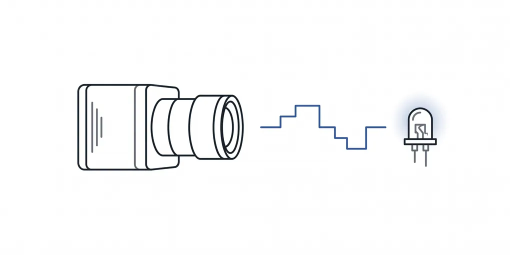
Synchronizing Camera Capture to a High-Intensity, Non-Standard LED
Modern cameras are designed to handle the flicker of a typical LED, but a light with a non-standard flicker frequency and a high intensity makes capturing video difficult.
Background
It is well-known that LEDs flicker, and while anti-flicker technology is built into many modern cameras, it is designed to handle the flicker that results from LEDs powered by mains power. For my scenario, the LED light source is driven by pulse width modulation, and importantly, its flicker frequency differs from the standard 50/60 Hz of mains power.
Capture Scenario
The important characteristics of my capture scenario are:
- No Control over Light Source
- High-Intensity Light (13k-20k+ lux)
- Non-Standard Flicker Frequency (not 50/60 Hz)
- Color Mixing (4 color channels)
Let’s look at each one…
No Control over Light Source
When controlling the light source is a feasible approach, it makes synchronization of the camera and the light a much simpler task. Unfortunately, controlling the light source and/or adding a controlled light source was out of the question in the setting that I was engineering for.
High-Intensity Light
The light is bright, 13,000 to 20,000+ lux, and my camera was close enough to oversaturate the sensor under any ordinary exposure. The conventional answer when lighting that causes overexposure cannot be avoided is to use a camera with high dynamic range (HDR), but depending on how it’s implemented, HDR introduces its own drawbacks, cost among them.
Non-Standard Flicker Frequency
Knowing that my light source was driven by pulse width modulation and that its switching frequency was non-standard, I determined that syncing the camera’s capture to the light would be beneficial, if not essential.
Color Mixing
The light I was capturing appears white, but a common technique known as color mixing was in use. Four color channels, each with their own duty cycle and offset, were being blended together. To the eye, and to any exposure long enough to integrate across a full PWM cycle, the colors blended into a steady white.
Solution
Addressing the saturation of the camera’s sensor was done via neutral-density filters and a short exposure, but due to the color mixing of the light source and the lack of synchronization, the captured color varied significantly frame-to-frame.
With the light’s internals inaccessible, synchronization had to be done with the light source’s output. A phototransistor aimed at the light, together with a simple circuit and microcontroller, convert the emitted light into a voltage that is then digitized, producing a waveform representing the combined color channels.
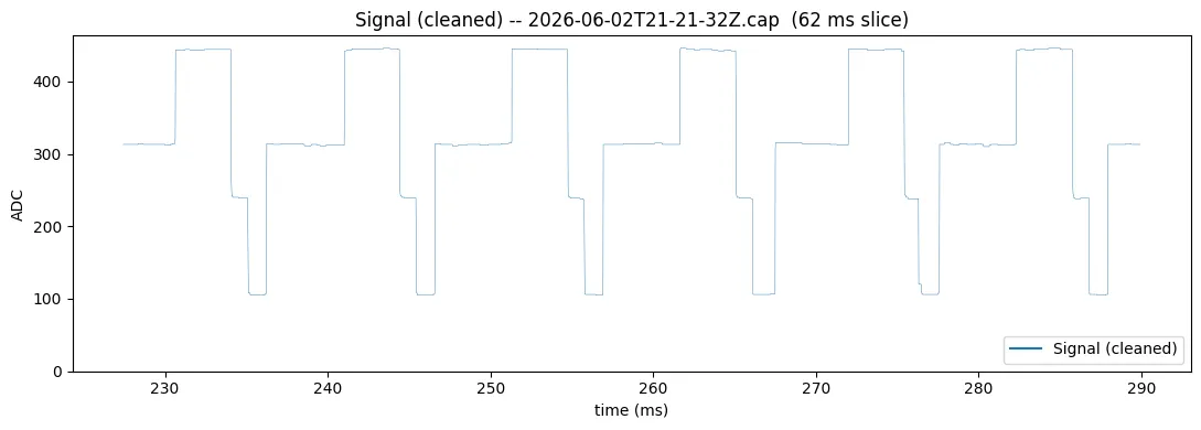
From there, the goal is not merely to catch a bright portion of the waveform but to land every trigger at the same phase of the cycle, so the same combination of color is captured frame after frame; drift in phase alters the color drastically, while a consistent phase holds it steady. A microcontroller running custom software samples the recovered signal and drives the camera’s trigger pin to do exactly that.
The second video below shows the result: stable color and brightness, with no pulsing or partially-lit frames, and as bonuses, no motion blur (due to global shutter and short exposure) and no need for a costly HDR sensor.
Before: Unsynchronized
The following video was captured with a machine vision camera, in the Master stream mode (i.e. no synchronization with the light).
After: Synchronized
The following video was captured with the same machine vision camera and under the same light source, but in the Trigger stream mode with a phototransistor and custom hardware/software driving the camera’s capture.
Drawbacks
The primary drawback of this approach is the requirement that the phototransistor be aimed at the light, and that the luminance must be sufficiently intense and consistent. This limits the applicability of the described solution. With that being said, additional efforts could be made to achieve a clean signal even if the phototransistor is not in close proximity of, and can not be directly aimed at, the light source.
Additionally, as the signal is indirectly measured, a fairly complex algorithm was needed to ensure consistent triggers.
Conclusion
The solution detailed in this article is generalizable to different switching frequencies and differing waveforms, which is necessary for my application. Furthermore, due to its affordability, it may be applicable to a wider range of applications.